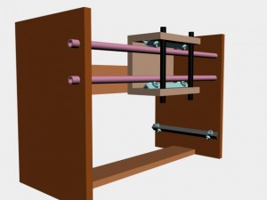
In the last post in this series, I talked about the design of the Z-axis for the CNC Router I am designing. In today’s post, I want to briefly discuss the design of the Y-axis. The Y-axis is essentially the same as the Z-axis except it is larger and is turned horizontal instead of vertical. The purpose of the Y-axis is to carry the Z-axis from one end of the table to the other.
In this design, the Z-axis travels from left to right along the steel tubes of the Y-axis. Although not shown in the graphic, a stepper motor will be installed on the left side of the Y-axis that will drive a lead screw that is responsible for the movement of the Z-axis. There are two bearing supports near the bottom of the Y-axis (one is hidden by the right side panel) that will ride along the edge of the table that fits between the two side panels of the gantry.
The brace mounted in the bottom of the gantry provides support and is the attachment point for the X-axis drive mechanism. I am being very brief in these early discussions because I am only covering design concepts at this stage. When I get into the actual construction, I will go into greater detail.
I hope when you come back next time I’ll have some design drawings for the X-axis and I’ll talk about that. Until then, stay safe, work hard, and as always, thanks for stopping by MVB Crafts.
Regards,

P.S.
If you enjoy reading articles like this, help us by supporting our advertisers. We can then continue bringing you quality content.
Thanks.


